TM-5-3805-254-14-P-2 - Page 158 of 894
TRUCK SERVICE MANUAL
SERVICE CHECKS
Operation Test
With two test gauges you know to be accurate,
disconnect one of the front brake chamber lines or
remove the plug from the unused brake chamber inlet
port, if this type, and install one of the test gauges.
The
other test gauge should be installed in a foot brake valve
delivery line.
Place the handle of the two-way valve in
the dry road position and make a foot valve application.
Readings on both test gauges should be the same.
Release the foot application and note that the air is
exhausted promptly at the exhaust port of the limiting
and quick release valve.
Place the handle of the two-way valve in the slippery
road position and apply the foot valve.
The reading on
the test gauge connected in the brake chamber or line
should be about one-half the reading on the test gauge
connected to the brake valve delivery line.
Leakage Test
With the two-way valve handle in the dry road
position, make and hold a foot valve application.
Check
the exhausts of both the two-way and limiting and quick
release valves for leakage.
Place the handle of the two-way valve in the slippery
road position.
Make a foot valve application and check
the exhaust of the two-way valve for leakage.
If the limiting and quick release valve or two-way
valve does not function as noted above or if leakage is
excessive, it is recommended that they be reconditioned
or replaced.
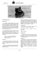
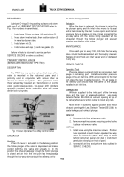
REMOVE AND REINSTALL.
Remove
To remove the limiting and quick release valve
assembly, disconnect all air lines at valve and remove
mounting bolts.
Install
Install valve in same location where removed using
same mounting bolts.
Connect brake chamber lines to
delivery ports of valve and brake valve delivery line to top
of inlet port and line from two-way valve to side inlet port.
The perform the tests listed in "SERVICE CHECKS".
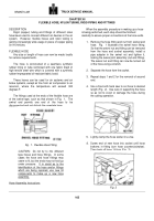
DISASSEMBLE
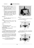
Remove the four capscrews that hold the valve cover
to the body.
Separate cover, gasket and body.
Push
piston assembly out of body.
If necessary, the piston
assembly can be dismantled and its component parts
serviced.
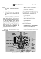
To disassemble the piston assembly, first
remove the piston grommets.
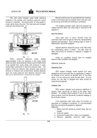
The boot type inlet and exhaust valves are
removable and serviceable.
They can either be cut or
pryed off the stem.
Remove the exhaust valve, valve guide and spring.
Pull the valve stem through the piston and remove
the inlet valve from its stem.
CLEANING AND INSPECTION
Clean all metal parts of both valves in good cleaning
solvent and dry thoroughly.
All rubber parts will be
replaced.
Check all metal seats for scratches or scores.
Polish seats with fine crocus cloth when they are nicked
or corroded.
Inspect all springs for cracks, distortion and
corrosion and replace where necessary.
REASSEMBLE
If an arbor press is available, the inlet and exhaust
valve boots should be pressed on the stem dry.
Without
an arbor press a little soap or water will make it easier to
press on the stem.
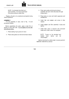
Install inlet valve boot on stem and insert in piston.
Position spring and valve guide over stem and press
exhaust valve boot on stem.
Lubricate body and cover bores, grommet and
grommet grooves and other areas of the piston with a
lubricant comparable to that listed in "LUBRICATION
SPECIFICATIONS" item 1.
Press piston assembly in body but with caution so
piston grommets are not damaged.
Position gasket and cover on body and install four
capscrews with lock washers.
156
BRAKES-AIR
Back to Top

