TM-5-3805-254-14-P-2 - Page 150 of 894
TRUCK SERVICE MANUAL
BREAKS-AIR
INSTALL
1. Block and hold vehicle by means other than air
brakes.
2. Drain air system.
3. To prevent early plugging of the filter, thoroughly
flush and clean reservoir before installing drain
valve.
4. Aerate any tank thoroughly if any solvents have
been used in the cleaning process.
NOTE:
When installing the automatic reservoir
drain valve equipped with a heater and thermostat,
first determine if the vehicle electrical system is
12volt or 24volt and that the heater/thermostat unit
is of the same voltage. The #14 gauge lead wire on
the valve should be connected to the "on" position
of the engine control or ignition switch.
Use an
8amp fuse for one valve, a 15amp fuse for two
valves and a 20amp fuse for three valves.
All
electrical connections must be waterproof.
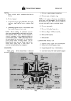
DISASSEMBLY
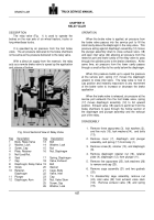
Refer to Fig.
13 for disassembly of valve and
proceed as follows:
1. Remove 4 capscrews and lockwashers.
2. Remove cover and sealing ring.
NOTE:
If the heater or thermostat has failed, the
entire cover must be replaced.
Do not remove the
thermostat cover plate.
It is moisture sealed and
removal could result in early thermostat failure.
3. Remove valve guide.
4. Remove inlet and exhaust valve.
5. Remove adapter and filter assembly.
6. Remove filter retainer.
7. Remove filter.
CLEANING AND INSPECTION
1. Cleaning solvent may be used on metal parts.
2. Rubber parts should be wiped clean.
3. Inspect all parts for wear or deterioration.
4. Clean and inspect filter and replace if clogged.
Back to Top

