TM-5-3805-254-14-P-2 - Page 154 of 894
TRUCK SERVICE MANUAL
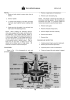
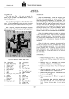
4. Remove screw (28) from body (1).
5. Remove piston assembly (18) and spring (16)
from body.
6. Remove snap ring (7), spring guide (8),
spring
(12), and shim washers (15).
7. Remove spring (16).
8. Remove "O"-ring (17) and vee-block seal (14).
9. Remove cap screws (22), lock washers (21),
end cap (24) and gasket (27).
10. Remove cage assembly and "O"-ring (20) from
body.
11. Hold exhaust valve (10), unscrew nut (26) and
remove exhaust valve spring (23) and inlet valve
(25) from cage assembly.
12. Remove snap ring (13), cap (10), air cleaner (9)
and screen (10A).
Inspection and Cleaning
1. Wash all metal parts in mineral spirits or
cleaning fluid.
2. Scrape old gasket material from mating surfaces
of end cap (24) and cage assembly.
3. Clean and wipe dry inlet valve (25) and exhaust
valve (19).
They must be replaced if nicked or
worn.
4. Examine inlet valve seat in cage assembly and
exhaust valve seat on piston (18).
They must be
free of nicks.
Crocus cloth may be used to
smooth off slight nicks; if nicks are too deep,
replace piston or cage.
5. Replace boot if cracked or deteriorated.
Assembly
1. Place spring (23) on stem of exhaust valve (19)
and install in cage with inlet valve (25) and nut
(26).
Tighten securely.
2. Install new "O"-ring (20) in body (1).
3. Use scratch marks to position gasket (27) and
cage
assembly,
install
lock
washers (21), cap
screws (22) and tighten securely.
4. Install new "O"-ring (17) and vee-block (14) on
piston (18).
5. Install shim washers (15) in piston (four normally
required) spring (12) shim washers (11) (two
normally required) and
secure in place with snap ring (7).
6. Apply light lubricant to inside bores of body.
Install piston assembly in body.
7. Install screw (28) with head of screw tight
against body.
8. Install plunger (6) in mounting plate (2),
position
mounting plate on body and secure in place with
three lock washers (3) and cap screws(4).
Tighten securely.
9. Install boot (5) in grooves in mounting plate.
NOTE:
The gap between the exhaust
valve and seat must be .06" minimum.
This may be checked by inserting a
feeler gauge through a delivery port.
Test
Released Position
Plug all cylinder ports.
Connect air supply and air
gauge to inlet port.
Check exhaust port with soapy
water.
No leakage allowed.
Applied Position
Connect air
supply
and air gauge to one cylinder
port.
Depress treadle or piston to allow 5 to 10 psi air
pressure to register on gauge in cylinder port.
Check
exhaust port with soapy water; a one inch soap bubble in
three seconds permissible.
Depress plunger of brake valve slowly so that brake
valve piston movement is also slight.
Note that pressure
gauge reading at cylinder port builds up in proportion to
pressure gauge reading at inlet port.
(The pressure
reading at cylinder port should become greater as
plunger is further depressed.) With plunger fully
depressed, both gauges should read alike.
While
plunger is depressed in this holding position, a one inch
soap bubble in three seconds at exhaust port is
permissible.
Coat the entire valve with soapy water especially
around gaskets, assembly screws,
and tubing fittings.
With brakes released or applied, no leaks are permitted.
If tightening the assembly screws or fittings does not
eliminate air loss, the brake valve must be disassembled
and reassembled correctly.
When tests determine that brake
valve
is
satisfactory, remove test gauges and air lines from valve.
Prevent the entrance of dirt in valve by plugging all ports
until valve can be reinstalled in air system.
152
BRAKES-AIR
Back to Top

