TM-5-3805-254-14-P-2 - Page 152 of 894
TRUCK SERVICE MANUAL
CHAPTER III
CHECK VALVES
ONE-WAY CHECK VALVE
DESCRIPTION
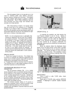
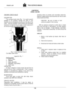
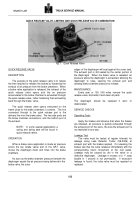
The one-way check valve (Fig.
1) is used to permit
passage of air pressure through the valve in one
direction only as indicated by the arrow on the side of the
valve.
They are installed in both primary and secondary
reservoirs to maintain the air supply in both reservoirs if
an air loss should occur ahead of the valve.
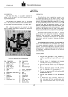
Fig. 1
Cross Sectional View of
One-Way Check Valve
Legend for Fig.
1
KeyDescription
1
BODY, Valve
2
SPRING
3
SEAL, Assembly
4
WASHER, Cap-to-Body
5
CAP, Valve
OPERATION
Air flow in direction of arrow moves the seal from its
seat and the air flow is unobstructed.
Flow in reverse
direction is prevented by seating of the seal by the
upstream air pressure and assistance of spring.
MAINTENANCE
Once each year or every 100, 000 miles check
operation (see SERVICE CHECKS).
SERVICE CHECKS
Depending upon installation, it may be easier or
necessary to completely remove check valve so that the
following checks may be made.
If
checking valves at primary and secondary reservoirs,
bleed air supply reservoir and disconnect air inlet to valve
and proceed as follows.
CAUTION:
Be sure to block or hold
vehicle to prevent it from moving.
With air pressure present at outlet side of check
valve and inlet open to atmosphere, use leak detector
tester to test for leakage.
A slight leakage is permitted.
However, if valve leaks excessively, the valve should be
replaced.
REMOVE
1. Block or hold vehicle by means other than air
brakes.
2. Drain all air reservoirs.
3. Disconnect air lines and remove check valve.
INSTALL
1. Check and, if required, clean or replace air line
to valve.
2. Install valve making certain that it is installed
correctly.
Arrow on outside of body indicates
direction of air flow through valve.
3. Check valve for leakage.
150
BRAKES-AIR
Back to Top

