TM-5-3805-254-14-P-2 - Page 743 of 894
TRUCK SERVICE MANUAL
TRANSMISSION
Para 6-1/6-3
Section 6.
INSPECTION AND REBUILD OF SUBASSEMBLIES
6-1.
SCOPE OF SECTION
6
This section describes the disassembly and assembly of
subassemblies that were removed in Section 5.
For
rebuild procedures, refer to the exploded views (foldouts
7 through 17) located at the end of this manual.
Reference is also made to line drawings and
photographs in this section.
6-2.
GENERAL INFORMATION FOR SUBASSEMBLY
REBUILD
a.
Tools, Parts, Methods.
Refer to paragraphs 4-2,
4-3 and 4-4.
b.
Cleaning, Inspection.
Refer to paragraph 4-5 for
cleaning and inspection procedures.
c.
Torque Specifications.
The specific torque value
for each threaded fastener is stated at each assembly
step.
Torque values are also presented in paragraph 4-
9.
d.
Wear Limits, Spring Data.
Refer to Section 8 for
wear limits and spring data.
e.
Plugs and Fittings.
Prior
to installation, apply a
small amount of nonhardening sealant (or Teflon tape)
into the threads of each plug.
Tighten the plugs
sufficiently to prevent leakage.
f. Clutch Pack Procedure.
Soak the friction-faced
clutch plates in transmission fluid for a minimum of 2
minutes prior to assembly.
6-3.
FLYWHEEL, LOCKUP CLUTCH, CONVERTER
TURBINE
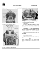
a. Disassembly (foldout 7)
(1)
Position
the
flywheel
assembly,
front
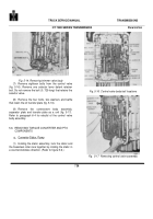
downward, on the work table (fig. 6-1).
(2)
Using two large screwdrivers or (prybars)
cushioned to prevent scratching(components)pry the
torque converter turbine free of the flywheel and lockup
clutch (fig. 6-1).
Back to Top


