TM-5-3805-254-14-P-2 - Page 748 of 894
TRUCK SERVICE MANUAL
TRANSMISSION
Para 6-4
HT 700D SERIES TRANSMISSIONS
(10)
Remove eight bolts 44while holding trimmer
cover 43 against spring pressure.
Relieve pressure and
remove cover 41.
(11)
Remove springs 27 and 28, valve stop 29,
trimmer plug 26, and trimmer valve 25.
(12)
Remove springs 32 and 33, stop 34, plug 31,
and valve 30.
(13)
Remove springs 37 and 38, stop 39, plug 36,
and valve 35.
(14)
Remove valve 42, spring 41 and stop 40.
(15)
Remove springs 47 and 48, stop 49, plug 46
and valve 45.
NOTE
In operations (16) through (24), below, the
components i n each bore are spring-loaded,
and must be restrained while removing the
retainer pins.
Also, before removing retainer
pins in operations (20), (21) and (22), the
adjusting rings must be marked, and each
identified with its bore, so they can be
reassembled into the same bores and at the
same positions in the bores.
(16)
Remove retainer pin 50, valve stop 54, spring
53, and valve 52.
NOTE
In earlier models, valve stop 54 consisted of two
separate pieces.
(17)
Remove retainer pin 51, spring spacer 57,
spring 56, and valve 55.
(18)
Remove retainer pin 63, spring 61, stop 62
and valve 60.
(19)
Remove retainer pin 72, valve plug 71, spring
69, valve stop 70, and valve 68.
(20)
Remove retainer pin 75, adjusting ring 80,
spring 78, valve stop
79, and valves 77 and 76.
(21)
Remove retainer pin 86, adjusting ring 85,
spring 83, valve stop 84, and valves 82 and 81.
(22)
Remove retainer pin 92, adjusting ring 91,
spring 89, valve
stop 90, and valves 88 and 87.
(23)
Remove retainer pin 96, valve stop 95, spring
94, and valve 93.
NOTE
In earlier models, valve stop 95 consisted of two
separate pieces.
(24)
Remove retainer pin 100, spring 98, valve stop
99, and valve 97.
NOTE
Refer to paragraph 6-2, above.
b. Assembly (B, foldout 16)
NOTE
Check the position of all valve assembly
components, the configuration of all valves and
plugs, and the identification of all springs before
installation.
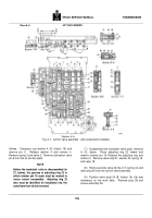
Refer to figure 6-7 for position and
configuration of components.
Refer to the
spring chart in Section 8 for identification of
springs.
(1)
Install components into bores A and B (fig. 6-
7), in the sequence indicated by numbers 1 through 5.
NOTE
All valves must move by their own weight (dry)
when installed.
(2)
Install spring spacer 57 and valve stop 54 (B,
foldout 16) into bores A and B (fig. 6-7).
Depress the
springs and install retainer pins 51 and 50 (B, foldout 16)
to retain spacer 57 and valve stop 54.
NOTE
In earlier models, valve stop 54 consisted of two
separate pieces.
(3)
Install components into bores C, D and E (fig.
6-7), in the sequence indicated by numbers 6 through 17.
(4)
Install components into bore F, in the
sequence indicated by numbers 18 through 22.
(5)
Install components into bore S (fig. 6-7), in
sequence indicated by numbers 65, 66 and 67.
(6)
Install trimmer cover 43 (B, foldout 16).
Compress the springs, and retain the cover with eight
1/4-20 x 5/8-inch bolts.
741
Back to Top


