TM-5-3805-254-14-P-2 - Page 764 of 894
TRUCK SERVICE MANUAL
TRANSMISSION
HT 700D SERIES TRANSMI SSIONS
Para 6-19/6-20
retainer rings to prevent damaging the piston projections.
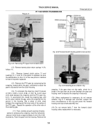
Remove four retainer rings, a retainer, and twenty
springs from each piston.
(5) Remove two step-joint sealrings 13 (A,
foldout 12) from the hub of support housing 18.
(6) Remove thrust bearing race
15 and needle
bearing 14.
NOTE
Refer to paragraph 6-2, above.
b. Assembly (A, foldout 12)
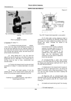
(1) Temporarily place piston 10 in the front piston
cavity of center support housing 18. Install springs 9 into
the pockets of the piston. Aline spring retainer 8 on the
four ejector pin bosses of the piston. Compress the
springs by forcing the retainer into the recess at the outer
edge of the center support w hen the retainer rings are
installed (fig. 6-45). Install a new self-locking retainer ring
7 on the ejector pins of each piston, using installer 58
(fig. 4-4). Remove the piston from the center support.
(2) Repeat the procedures in (1), above, to
assemble items 21 through 24 (A, foldout 12) into the
rear cavity of support housing 18.
NOTE
If the pistons are not forced to the
bottom of their cavities during installation
of self-locking retainer rings 7 and 24,
proper clutch clearance cannot be
established.
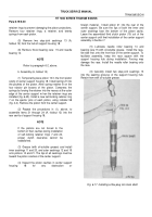
(3) Grease (with oil-soluble grease) and install
inner sealrings 11 and 20, and outer sealrings 12 and 19
onto pistons 10 and 21. The lips of all sealrings must be
toward the piston cavities of the center support.
(4) Inspect the piston cavities in center support
housing
18
for
any
obstruction
or
foreign material.
Install piston 21 into the rear of the
center support. Be sure the lips of both the inner and
outer sealrings face the bottom of the piston cavity.
Leave the assembled third clutch piston (10) out of the
center support until final installation of the center support
assembly in Section 7.
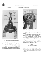
(5) Lubricate needle roller bearing 14 and
bearing race 15 with oil-soluble grease.
Install the race,
flat side first, onto the front hub of the center support. To
facilitate assembly, keep the race square with the
support housing hub during installation. Forcing may
damage the race. Install the needle roller bearing onto
the race.
(6) Carefully install two step-joint sealrings 13
into the sealring grooves of the support housing hub.
Retain them with oil-soluble grease.
Back to Top


