TM-5-3805-254-14-P-2 - Page 770 of 894
TRUCK SERVICE MANUAL
TRANSMISSION
Para 6-2316-24
HT 700D SERIES TRANSMI SS IONS
(3) Remove oil seal 42 (A, foldout 14) from the
transmission housing.
4) If replacement of breather 1 is necessary, remove
it from the housing.
(5) Inspect neutral safety switch plug 41, washer 40,
and reverse signal plug 4 for damage.
If damaged,
replace with new parts.
(6) If it is necessary to replace nameplate 6, remove
one drive screw 5.
NOTE
All replacement parts ordered refer to the
information both nameplate Therefore it is
imperative that the new nameplate be stamped
with identical information.
NOTE
Refer to paragraph 6-2, above.
b.
Assembly (A, foldout 14)
(1) Coat the inside diameter of oil seal 42 (A,
foldout 14) with a seal lubricant, and the outside diameter
with a nonhardening sealant.
Install the oil seal, lip first,
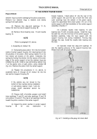
into the transmission housing (Fig. 6-62).
Use installer
32 (Fig. 4-3) to properly locate the seal in the housing.
The seal must clear the chamfer in the housing bore.
(2) Hold detent lever 34 (A, foldout 14) so that the
selector valve pin extends toward the inside of the
housing (Fig. 6-61).Slide the manual shaft through the
opening in the housing, oil seal, and slot in the detent
lever.
Install the locknut and retainer pin. Tighten the
locknut to 15 to 20 pound feet (20 to 27 Nm) torque.
(3) If breather 1 (A, foldout 14) was removed,
install the breather.
(4) If removed, install nameplate 6 and drive screw
5 (refer to a(6), and note, above).
6-24.
LOW PLANETARY CARRIER ASSEMBLY
NOTE
Disassemble the planetary assembly only if
there is evidence of undue wear or damage.
Failure of one pinion requires replacement of
the entire set, because the pinions are
selectively matched.
a.
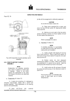
Disassembly (A, foldout 15) (1) Using a 31/32-inch
drill, centered accurately, drill into one end of each pinion
pin 20 until the swaged end is sufficiently weakened.
CAUTION
Do not drill into metal of carrier 19.
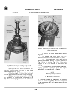
(2) Place carrier assembly 18 in a press, and
press four pins 20 from carrier 19, shearing the drilled
ends of pins 20.
Back to Top


