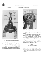
TM-5-3805-254-14-P-2 - Page 775 of 894
TRUCK SERVICE MANUAL
TRANSMISSION
Para 6-30
INSPECTION AND REBUILD
a.
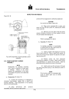
Disassembly ( A foldout 13)
(1) Using a 5/8-inch drill, centered accurately, drill
into one end of each pinion pin 12, until the swaged end
is sufficiently weakened.
CAUTION
Do not drill into metal of carrier assembly 6.
(2) Place carrier assembly 5 on a press bed.
Support the carrier in a manner such that no stress will
be placed on the swaged pins (smaller diameter) that do
not retain the pinions.
Press six pinion pins 12 from
carrier assembly 5, shearing the drilled ends of pins 12.
(3) Remove as a unit, each of the six pinion groups
consisting of pinions 10, thrust washers 8 and 11, and
needle roller bearing 9.
Remove the bearings
from the
pinion bores.
(4) Inspect carrier assembly 6 for relative
movement bet w e e n the remaining parts.
If looseness
is detected, replace the assembly.
NOTE
Refer to paragraph 6-2, above.
b.
Assembly (A,foldoutl3)
NOTE
To facilitate assembly, it is permissible
to freeze pinion pin 12 or heat carrier 6
before pinion installation.
(2) Install a needle roller bearing 9 (A, foldout 13)
into the bore of each pinion 10.
Place a steel thrust
washer 11(first) and a bronze thrust washer 8 (second)
onto each face of pinion 10.
(3) Place the carrier assembly in a press.
Support
the carrier in such a manner that no stress will be placed
on the swaged pins when the pinion pins are installed.
Place a pinion group (as assembled in (2), above) into
the carrier.
(4) Carefully aline the parts of the pinion group
with the pinion pin holes in the carrier assembly, and
install pinion pin 12 (A foldout 13).
Press the pinion pin
through the carrier and pinion group to the dimension
shown in figure 6-68.
Fig. 6-68.
Components of front planetary carrier
assembly
768
Back to Top


