TM-5-3805-254-14-P-2 - Page 767 of 894
TRUCK SERVICE MANUAL
TRANSMISSION
INSPECTION AND REBUILD
Para6-22
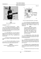
Fig. 6-54.
Removing speedometer driven gear bushing
Fig. 6-56.
Governor support pin location
(2) If removed, install the bearing front snapring
into the rear cover (Fig. 6-55) Install plugs, if removed,
into the rear cover.
(3) If removed, install the governor support pin to
the dimension shown in figure 6-56.
Accuracy of
location and concentricity with the governor bore is of
the utmost importance when installing the pin.
(4) If removed, install a new speedometer driven
gear bushing (Fig. 6-55).
Use installer 21 (Fig. 4-2) to
seat the bushing in the rear cover.
(5) Lubricate sealrings 5 and 6 (A, foldout 16) with
transmission fluid, and install them into the grooves of
piston 4.
The lip of each sealring must face the rear of
the piston (toward piston cavity in rear cover).
(6) Using inner seal protector 12 (fig.4-2), carefully
install the piston into the rear cover (Fig. 6-57).
Use
extreme care to prevent the lip of either seal folding
back over itself.
If installation is difficult, remove the
piston and check the seal and cover bore before again
attempting installation.
Fig. 6-55.
Installing speedometer driven gear bushing.
760
Back to Top


