TM-5-3805-254-14-P-2 - Page 774 of 894
TRUCK SERVICE MANUAL
TRANSMISSION
Para 6-26 /6-30
HT 700D SERIES TRANSMI SS IONS
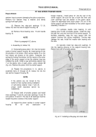
flat race 20 onto bearing 21, retaining each with oil-
soluble grease.
(9) At the rear of carrier assembly 25, install low sun
gear 24, extended hub first, over the rear end of shaft 11.
Retain it with snapring 23.
(10) Position the assembly, front upward, and
support the rear of carrier assembly 25.
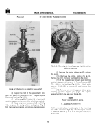
(11) Install center planetary carrier assembly 10,
outer splines upward, into drum 17.
Install front
planetary ring gear 9, outer splines first, into drum 17.
Retain gear 9 with snapring 8.
(12) Install thrust washer 7 onto shaft 11.
Install
sun gear and shaft assembly 6, larger diameter first, onto
shaft 11.
(13) Install thrust washer 5 onto the rear hub of
front planetary carrier assembly 4.
Install carrier
assembly 4 so that thrust washer 5 seats on the front of
center planetary carrier assembly 10.
(14) Install thrust washer 3, sun gear 2, and thrust
washer 1 into the front of front planetary carrier assembly
4.
6-29.
FLEX DISK ASSEMBLY
a.
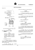
Disassembly (A, foldout 7)
(1) If flex disk assembly 2 has not been removed
from
the engine crankshaft, remove it.
(2) Remove twelve self-locking bolts 9 and
separate plate 8, flex disks 6 and 7, and hub assembly 3.
NOTE
Refer to paragraph 6-2, above.
b.
Assembly (A, foldout 7)
(1) Install flex disk6 onto hub assembly 3, alining
the dowel pin hole in the disk with pin 5.
Washers
attached to disk 6 must face toward hub assembly 3.
(2) Install flex disks 7 in the same manner.
(3) Install plate 8, alining the plate with dowel pin 5.
(4) Install twelve self-locking, 1/2-20 x 3/4-inch
bolts 9 through plate 8, disks 6 and 7, and into hub
assembly 3.
Tighten the bolts to 96 to 115 pound feet
(130 to 156 Nm) torque.
(5) Install flex disk assembly 2 onto the engine
crankshaft.
Refer to the vehicle service manual for bolt
torque-value.
6-30.
FRONT PLANETARY CARRIER ASSEMBLY
NOTE
Refer to paragraph 6-26 for removal from gear
unit. Disassemble the planetary only if there is
evidence of undue wear or damage.
Failure of
one pinion requires replacement of the entire
set because the pinions are selectively
matched.
767
Back to Top

