TM-5-3805-254-14-P-2 - Page 768 of 894
TRUCK SERVICE MANUAL
TRANSMISSION
Para 6-22
HT 700D SERIES TRANSMISSIONS
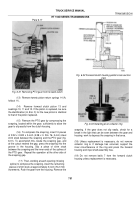
Fig. 6-57.
Installing piston into rear cover
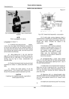
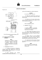
Fig. 6-58 Installing output shaft orifice plug
Figure 6-58.
Installing output shaft orifice plug.
(7) Remove the seal protector.
Install 30 springs
(Fig. 6-53).
Install the spring retainer, cupped side first,
onto the springs.
(8) Using compressor components 2 and 3 (Fig. 4-
2), compress the retainer and springs (Fig. 6-53).
Install
the snapring, and remove the compressor.
(9) If the orifice plug was removed f r o m the output
shaft, install a new plug, orificed side first (Fig. 6-58).
Use installer 34 (Fig. 4-3) to properly position the plug in
the shaft.
In each model, the plug must clear the
chamfer at the front of the plug bore in the output shaft.
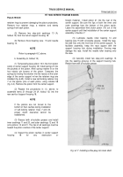
(10) If the bushing was removed from the front of the
output shaft, install a new bushing (Fig. 6-59).
Locate the bushing in the shaft with installer 31
(Fig. 4-3).
The bushing is 0.
145 to 0.
165 inch (3.
68
to 4.19 mm) from the front of the shaft.
(11) Press
the
speedometer drive gear, spacer
sleeve, and bearing onto the rear output shaft (Fig. 6-
52).
Install the assembled shaft.
Fig. 6-58 Installing output shaft orifice plug
(12) On assemblies before S/N 5660, install the
bevelled snapring (bevel toward rear of transmission) as
shown inf igure 6-51 On later transmissions, the snapring
is not bevelled.
Be certain that the proper snapring is
used to match the groove in the housing.
Be sure the
snapring is expanded fully into the groove.
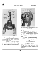
(13) Coat the outer circumference of the output shaft
oil seal with nonhardening sealer.
Install the oil seal,
spring-loaded lip first.
Use installer 26 and driver handle
28 (Fig. 4-3) to locate the rear of the seal 0.
60 to 0.70
inch (15.
2 to 17.8 mm) in front of the parking brake
mounting surface plane (fig.
.
761
Back to Top

