TM-5-3805-254-14-P-2 - Page 772 of 894
TRUCK SERVICE MANUAL
TRANSMISSION
HT 700D SERIES TRANSMISSIONS
Para 6-25/6-26
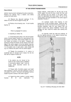
(3) Turn the piston assembly over, and cut the our
retainer rings while depressing the retainer (Fig. 6-65).
NOTE
Any method of removal except cutting may
damage the risers on the piston.
Damage will
lessen the holding power of retainer rings
installed thereafter.
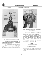
(4) Remove the spring retainer and 28 springs
from the piston (Fig. 6-55).
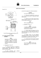
(5) If replacement is necessary, remove dowel pins
11 and 12, and orifice plug 13 (A, foldout 15) from
adapter housing 10.
NOTE
Refer to paragraph 6-2, above.
b.
Assembly (A, foldout 15)
(1) If removed, install new dowelpins 11 and 12
into housing 10.
They must project 0.
360 to 0.400
(9.15 to 10.16 mm) above the front face of the adapter
housing.
Install orifice plug 13 (if removed) flush with, or
to 0.
060 inch below the front face of the housing.
(2) Place piston 6 in the piston cavity of housing
10.
Be sure it is firmly bottomed in the cavity.
(3) Install 28 springs 5 into their recesses in the
piston.
Install retainer 4, so that its offset tangs are
upward, onto the piston and springs.
(4) Using installer 58 (Fig. 4-4), install four retainer
rings 3 (A, foldout 15).Press each ring into place until the
adjacent retainer tang bottoms in the counterbore of the
adapter housing.
CAUTION
Failure to install the retainer rings properly can
result in transmission damage or malfunction.
If installed too far onto the risers, proper clutch
clearance cannot be obtained .If not installed
far enough, the retainers may fall off.
Back to Top


