TM-5-3990-263-13-P - Page 328 of 728
Table
1.
Operator Preventive Maintenance Checks and Services - Continued
ITEM
NO.
INTERVAL
ITEM TO BE
CHECKED OR
SERVICED
PROCEDURE
EQUIPMENT
NOT READY/
AVAILABLE IF:
1
2
3
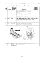
Figure 6.
Control Valve.
Inspect air cylinder (Figure 6, Item 2) and guard (Figure
6, Item 3) for damaged or missing hardware.
9
Before
Left and Right
Front Pin Locks
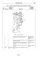
Check locking mechanism (Figure 7, Item 1) for
damaged or missing parts.
Front pin lock is damaged
or has missing parts.
1
2
2
3
3
1
Figure 7.
Front Pin Locks.
Check front pin lock wear pad (Figure 7, Item 2) for
excessive wear. Notify Field maintenance to turn over
wear pad (Figure 7, Item 2) if it is worn to within 1/16 inch
(1.59 mm) of screw heads, or if top edge is worn down
to 1/16 inch (1.59 mm) of metal contact. If bottom edge
has already been worn down, notify Field maintenance
to replace wear pad (Figure 7, Item 2).
Pull locking handle (Figure 7, Item 3) to see if assembly
disengages.
Front pin lock does not
engage
TM 5-3990-263-13&P
0035
0035-6
Back to Top


