TM-5-5420-202-20-1 - Page 631 of 1020
4-414.10
Change 6
TM 5-5420-202-20-1
DETAILED TROUBLESHOOTING PROCEDURE
VEHICLE OPERATION – HULL POWER
(Continued)
Symptom-31.1
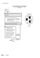
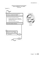
First Technician (Commander’s Station)
•
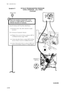
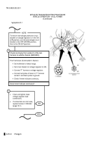
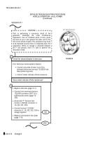
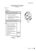
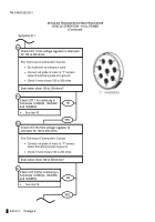
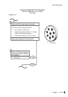
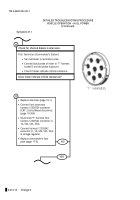
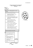
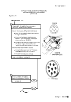
Connect red probe of meter to pin B on
bulkhead disconnect harness 12326539 and
black probe to ground.
•
Check if meter indicates infinite resistance.
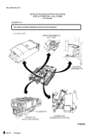
Check for shorted diodes in alternator.
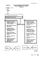
Does meter indicate infinite resistance?
14
NO
YES
•
Replace alternator (page 10-1).
•
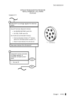
Connect front accessory harness
12326539 connector (CKT 2) to
bulkhead disconnect (page 10-
269).
•
Disconnect “T” harness from
harness 12326542 connector (1,
1A, 532, 533, 534)
.
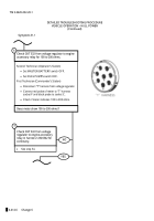
•
Connect harness 12326542
connector (1, 1A, 532, 533, 534) to
voltage regulator.
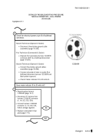
•
Replace commander’s floor plate
(page 17-9).
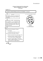
Prior to performing a resistance check of the
generator,
discharge
the
radio
interference
suppressor. Use an insulated piece of wire, place
one end on pin F and ground the other end of the
wire to the vehicle chassis. This procedure may have
to be repeated several times to completely drain the
suppressor. When no voltage is indicated between
pin F and ground, then it is safe to perform the
resistance check.
CAUTION
15
12326539
Back to Top

