TM-5-5420-202-20-3 - Page 541 of 1060
TM 5-5420-202-20-3
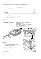
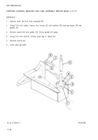
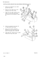
SHIFTING CONTROL BRACKET AND LINK ASSEMBLY REPAIR (Sheet 4 of 11)
10.
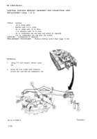
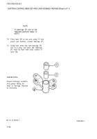
Using 9/16 inch wrench, remove bolt
(Q).
11.
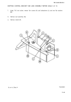
Using 9/16 inch socket and extension,
remove three screws (R) and lockwashers (S)
securing bracket assembly (T) to hull.
12.
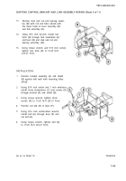
Remove bracket assembly (T) and shield
(U) from hull wall.
DISASSEMBLY:
1.
2.
3.
4.
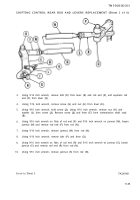
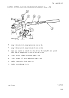
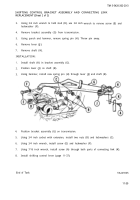
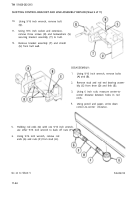
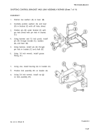
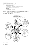
Using 9/16 inch wrench, remove bolts
(A) and (B).
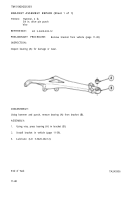
Remove stud and rod end bearing assem-
bly (C) from lever (D) and link (E).
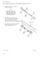
Using 6 inch rule, measure center-to-
center distance between holes in rod
ends.
Using pencil and paper, write down
center–to-center distance.
5.
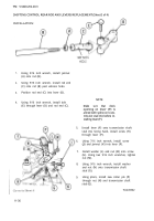
Holding rod ends (G) with one 9/16 inch wrench,
use other 9/16 inch wrench to back off nuts (F).
6.
Using 9/16 inch wrench, remove rod
ends (G) and nuts (F) from stud (H).
Go on to Sheet 5
11-44
TA249310
Back to Top

