TM-5-5420-228-24 - Page 359 of 750
TM 5-5420-228-24
OUTLET TO RELIEF VALVE MOUNT HOSE ASSEMBLY (CR)
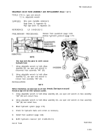
TOOLS: 12 in. adjustable wrench
1-1/4 in. open end wrench
SUPPLIES:
Drip pans (suit able containers)
Rags (Item 12, Appendix D)
Pipe tape (Item 19, Appendix D)
REFERENCE:
LO 5-5420-202-12
REPLACEMENT (Sheet 1
of 1)
PRELIMINARY PROCEDURES:
Remove front quadrant (page 3-45)
Relieve hydraulic pressure (page 3-71)
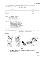
Use rags and drip pans to catch excess
hydraulic fluid.
1.
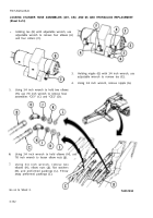
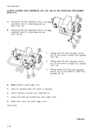
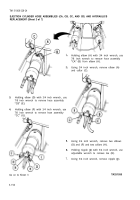
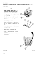
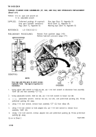
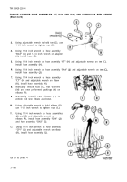
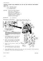
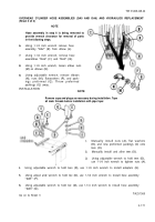
Holding elbow (A) with adjustable wrench, use
1-1/4 inch wrench to remove hose assembly “CR”
(B).
2.
Holding elbow (C) with adjustable wrench, use 1-1/4 inch wrench to remove hose assembly
“CR” (B).
INSTALLATION:
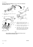
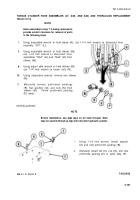
NOTE
Before installation, use pipe tape on all male threads. Start tape on second
thread so tape will not enter hydraulic system.
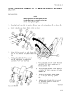
1.
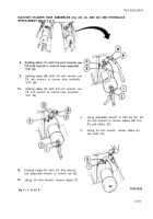
Holding elbow (A) with adjustable wrench,
“CR” (B).
2.
Holding elbow (C) with adjustable wrench,
“CR” (B).
3.
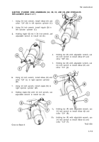
Bleed hydraulic system (page 3-72).
use 1-1/4 inch wrench to install hose assembly
use 1-1/4 inch wrench to install hose assembly
4.
Check for hydraulic leaks and correct as necessary.
5.
Install front quadrant (page 3-46).
6.
Service hydraulic reservoir (LO 5-5420- 202-12).
End of Task
3-162
TA251561
Back to Top

