TM-5-5420-228-24 - Page 373 of 750
TM 5-5420-228-24
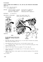
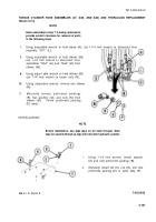
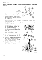
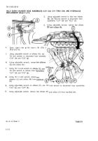
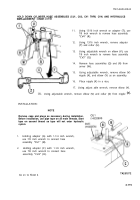
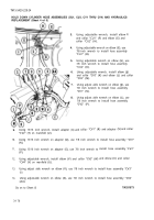
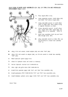
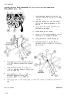
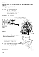
HOLD DOWN CYLINDER HOSE ASSEMBLIES (CU1, CU2, CV1 THRU CV4) AND HYDRAULICS
REPLACEMENT (Sheet 4 of 5)
9.
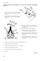
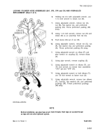
Using 13/16 inch wrench, install adapter
“CV2” (T) on manifold (U).
3.
4.
5.
6.
7.
8.
Using adjustable wrench, install elbow
and collar “CU1" (F) and elbow (G) and
collar “CU2” (H).
Using adjustable wrench on elbow (E), use
(E)
7/8
inch wrench to install hose assembly
“CU1” (B).
Using adjustable wrench on elbow (G), use
7/8 inch wrench to install hose assembly
“CU2" (D).
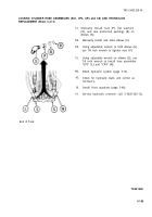
Using adjustable wrench, install elbow (J)
and collar “CVI” (K) and elbow (L) and collar
“CV2" (M).
Using adjust able wrench on elbow (J), use
7/8 inch wrench to install hose assembly
“CV1" (N).
Using adjust able wrench on elbow (L), use
7/8 inch wrench to install hose assembly
“CV2” (P).
(Q)
and collar “CV1“ (R) and adapter (S) and collar
10.
Using 13/16 inch wrench on adapter (Q), use 7/8 inch wrench to install hose assembly “CV1”
(N).
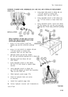
11.
Using 13/16 inch wrench on adapter (S), use 7/8 inch wrench to
(P).
12.
Using adjustable wrench, install elbow (V) and collar “CV3” (W)
“CV4” (Y) on manifold (U).
install hose assembly ‘CV2"
and elbow (X) and collar
13.
Using adjust able wrench on elbow (V), use 7/8 inch wrench to install hose assembly “CV3”
(z).
14.
Using adjustable wrench on elbow (X), use 7/8 inch wrench to install hose assembly “CV4
n
(AA).
Go
on to Sheet
5
TA251573
3-176
Back to Top

