TM-9-1290-365-24-P - Page 62 of 334
ARMY TM 9-1290-365-24&P
3.3.3 Materials Required
. Repair materials and other consumable item requirements are listed
in Table 3-8.
Table 3-8. Materials Required
Nomenclature
Part/Spec. No.
Appendix F
Item No.
Adhesive
S1184
3
Adhesive
S1125
2
Label
43-143
10
Primer
747-55
17
Primer
MIL-S-22473, Grade AA
20
3.3.4 General Repair Requirements
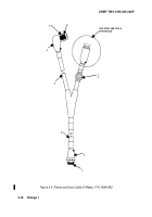
. Refer to Figure 3-4. Repair or replace cable connectors
as follows:
CAUTION
Using excess force when cutting boot may cause damage to wiring inside boot.
NOTE
Before replacing a connector, ensure that the replacement connector matches
exactly the connector to be replaced.
a. Using sharp knife, carefully cut boot (3).
b. Pry boot (3), off of backshell (2) and cable (4).
c. Using connector pliers (soft jaw), remove backshell (2) from connector body (1 ) and
slide away from connector (1).
d. Tag and label wires.
e. Using pin extractor tool, remove damaged pin and wire from connector body. Remove
serviceable pins and wires also to facilitate installation of new boot (3).
f. Remove connector (1) from cable (4).
g. Move backshell (2) away from end of cable (4).
h. Cut wire as close as possible to end of damaged pin.
i. Strip insulation from wire as required to ensure that wire will seat properly in pin.
Using crimping tool, crimp pin to wire.
NOTE
Failure to place heat shrink and backshell on cable at this point and in correct
sequence will require later removal of connector from cable to facilitate install
on of boot and backshell.
k. Slide new boot (3) on cable (4).
l. Using insertion tool, insert pins into connector body (1).
3-14
Back to Top


