TM-9-1290-365-24-P - Page 70 of 334
ARMY TM 9-1290-365-24&P
3.3.8 1553 Stub Repair Procedures
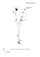
. Refer to Figure 3-9. Assembly and disassembly as
follows:
3.3.8.1 DISASSEMBLY Disassemble 1553 stub as follows:
CAUTION
Using excess force when cutting boot may cause damage to wiring inside boot.
a. Using sharp knife, carefully cut boot (1).
b. Pry boot off 1553 Stub and cable.
c. Remove three screws (3) from 1553 Stub (2).
d. Pull out carefully 1553 CCA (4).
e. Tag and label wires.
f. Disconnect by soldering TP1, TP3, TP5, and TP6.
g. Unscrew carefully connector body (5) from 1553 Stub (2).
h. Tag and label wires.
i. Use pin extraction tool to remove connector (5) J3 pins.
j. Pull out 1553 CCA (4).
k. Remove two screws (6) from 1553 CCA (4).
l. Replace damaged part T1 or R1, R2, as necessary.
3.3.8.2 ASSEMBLY. Assemble 1553 stub as follows:
a. Attach 1553 CCA (4) to 1553 Stub (2).
b. Attach terminal lug and fasten two screws (6).
c. Push in 1553 CCA (4).
d. Using insertion tool, insert pins into connector J3 body (5).
e. Apply primer to threads of connector body (5) and 1553 Stub (2).
f. Apply sealing compound to threads of connector body (5) and 1553 Stub (2).
g. Fasten carefully connector body (5) to 1553 Stub (2).
h. Slide new boot on cable.
i. Pull out carefully 1553 Stub and connect by soldering TP1, TP3, TP5, and TP6.
j. Push in 1553 CCA (4).
k. Fasten three screws (3).
I. Apply S1184 adhesive to inside of boot (1) to bond with cable shield and 1553 Stub (2).
m. Apply S1125 adhesive to outside of boot (1) for bonding to cable jacket and 1553 Stub
(2).
n. Place boot (1) on 1553 Stub (2).
o. Using heat gun to apply heat uniformly to boot (1) until boot shrinks to form secure seal
around 1553 Stub (2) and cable.
3-22
Back to Top


