TM-9-1290-365-24-P - Page 74 of 334
ARMY TM 9-1290-365-24&P
3.4.3. Materials Required
. Repair materials and other consumable item requirements are
listed in Table 3-11.
Table 3-11. Materials Required
Nomenclature
Part/Spec. No.
Appendix f
Item No.
Adhesive
S1184
3
Adhesive
S1125
2
Label
43-143
10
Primer
747-55
17
Primer
MIL-S-22473, Grade AA
20
Insulating Tube
M22129CLR22AWG
25
Resistor
75 ohms, 1%
28
3.4.4. General Repair Requirements
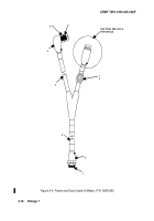
. Refer to Figure 3-10. Repair or replace connector as
follows:
NOTE
The following procedure applies to connector P1.
NOTE
Before replacing a connector, ensure that the replacement connector matches
exactly the connector to be replaced.
a. Using connector pliers (soft jaw), remove shorting cap (1) from connector body (2) and
slide away from connector (2).
b. Tag and label wires.
c. Using pin extraction tool, remove damaged pin and wire from connector body (2).
d. Using crimping tool, crimp pin to 75 ohm fixed film resistor lead. Cover with insulating
tube.
e. Using insertion tool, insert pins into connector body (2).
NOTE
Failure to perform continuity check at this point may require complete
disassembly of connector to correct improperly terminated connector pins.
f. Perform continuity test of cable in accordance with para. 3.4.6. If cable checks good,
proceed to step g.
g. Using small wire brush, clean sealing compound residue from threads of connector
body (2) and shorting cap (1 ).
h. Apply primer to threads of connector body (2) and shorting cap (1).
i. Apply sealing compound to threads of connector body (2) and shorting cap (1).
j. Install shorting cap (1) on connector body (2) and torque to 3.7 ft Ib (5 N.m).
3-26
Back to Top


