TM-9-2320-209-34-2-2 - Page 569 of 899
TM 9-2320-209-34-2-2
FRAME 3
1.
2.
3.
4.
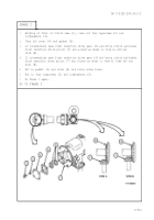
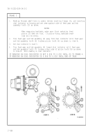
Working through shaft hole in power leveler mounting flange (1), mount dial
indicator on housing and set stem against side of reduction drive gear tooth
(2) as shown.
NOTE
When measuring backlash, make sure that first reduction
drive pinion (3) does not turn. If pinion turns, backlash
readings will be wrong.
Turn drive gear (4) away from dial indicator until drive gear tooth (5) touches
pinion tooth (6) as shown in view A.
Set dial indicator to read 0.
Turn drive gear (4) towards dial indicator until drive gear tooth (7) touches
either side o-f pinion tooth (6) as
indicator.
IF READING ON DIAL INDICATOR IS
IF READING ON DIAL INDICATOR IS
shown in view B.
Note reading on
-
dial
NOT 0.006 TO 0.024 INCH, GO TO FRAME 4.
0.006 TO 0.024 INCH, END OF TASK
17-552
Back to Top


