TM-9-2320-272-23-2 - Page 1183 of 1417
INSTALLATION - Continued
18.
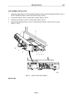
Route heat control cable (Figure 9, Item 13) and defroster control cable (Figure 9, Item 1) through diverter
brackets (Figure 9, Items 6 and 7).
19.
Install heat control cable (Figure 9, Item 13), defroster control cable (Figure 9, Item 1), and spring nuts
(Figure
9,
Items
2
and
11) on control panel rods (Figure 9, Items 5 and 9).
20.
Install cotter pins (Figure 9, Items 12 and 16) on control rods (Figure 9, Items 5 and 9).
21.
Install retaining clips (Figure 9, Items 4 and 8), cables (Figure 9, Items 1 and 13), and clamps
(Figure
9,
Items
3
and
10) on diverter brackets (Figure 9, Items 6 and 7) with screws
(Figure
9.
Items
14
and
15).
M9797DAA
4
10
11
12
13
14
15
16
5
6
7
8
9
3
2
1
Figure 9.
Instrument Cluster Installation.
TM 9-2320-272-23-2
0310
0310-12
Back to Top


