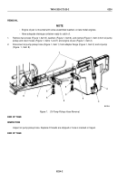
TM-9-2320-272-23-2 - Page 581 of 1417
INSTALLATION
1.
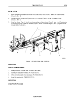
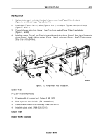
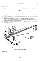
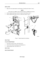
Apply antiseize tape to male pipe threads of adapter (Figure 2, Item 7) and elbow (Figure 2, Item 3).
NOTE
Ensure elbow is less than 1/8 turn from final position to allow room for installation of front
sump tube.
2.
Install adapter (Figure 2, Item 7) on oil pan (Figure 2, Item 2), and elbow (Figure 2, Item 3) on oil pump
(Figure
2,
Item
1).
3.
Install two nuts (Figure 2, Item 5) and bushings (Figure 2, Item 4) on sump tube (Figure 2, Item 6), and slide
toward center of sump tube.
4.
Position one end of sump tube (Figure 2, Item 6) on adapter (Figure 2, Item 7), and start elbow
(Figure
2,
Item
3) in other end of sump tube. Turn elbow to tighten into final position, pressing front sump
tube into elbow and aligning front sump tube with elbow.
5.
Connect sump tube (Figure 2, Item 6) to adapter (Figure 2, Item 7) and elbow (Figure 2, Item 3) by tightening
two nuts (Figure 2, Item 5).
1
M0027DAA
3
7
5
4
4
6
5
2
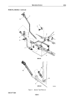
Figure 2.
Front Sump Tube Installation.
END OF TASK
TM 9-2320-272-23-2
0226
0226-4
Back to Top

