TM-9-2320-272-23-2 - Page 744 of 1417
INSTALLATION M939/A1
1.
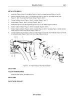
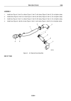
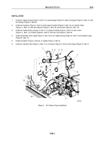
Install filter (Figure 4, Item 13) and elbow (Figure 4, Item14) on intake manifold (Figure 4, Item 12).
2.
Position grommet (Figure 4, Item 17) on indicator tube (Figure 4, Item 16), and install indicator tube
(Figure
4,
Item
16) and grommet through firewall (Figure 4, Item 1).
3.
Connect indicator tube nut (Figure 4, Item 2) to elbow (Figure 4, Item 11).
4.
Install adapter (Figure 4, Item 9) on elbow (Figure 4, Item 11).
5.
Install plate (Figure 4, Item 8) and gasket (Figure 4, Item 7) over adapter (Figure 4, Item 9).
6.
Install air cleaner indicator (Figure 4, Item 6) on adapter (Figure 4, Item 9).
7.
Install air cleaner indicator (Figure 4, Item 6) on gasket (Figure 4, Item 7) and plate (Figure 4, Item 8) with two
screws (Figure 4, Item 5) and locknuts (Figure 4, Item 10).
8.
Connect indicator tube nut (Figure 4, Item 15) to elbow (Figure 4, Item 14) and install plate (Figure 4, Item 8)
on instrument panel (Figure 4, Item 3) with four screws (Figure 4, Item 4).
M10262DAA
2
11
10
9
8
7
6
5
4
3
13
12
14
15
16
17
1
Figure 4.
Air Cleaner Indicator and Tube Installation.
END OF TASK
FOLLOW-ON MAINTENANCE
Install left splash shield. (TM 9-2320-272-10)
END OF TASK
END OF WORK PACKAGE
TM 9-2320-272-23-2
0247
0247-5/6 blank
Back to Top

