TM-9-2320-272-23-3 - Page 1242 of 1469
INSTALLATION - Continued
9.
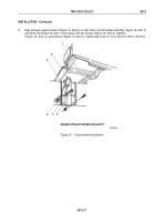
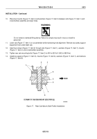
Align exhaust support bracket (Figure 16, Item 6) on right side of crossmember assembly (Figure 16, Item 5)
and frame rail (Figure 16, Item 1) and secure with two screws (Figure 16, Item 2), washers
(Figure
16,
Item
3), and locknuts (Figure 16, Item 4). Tighten eight nuts to 110 to 120 lb-ft (149 to 153 N·m).
M10220DAA
1
2
3
4
5
6
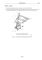
EXHAUST PIPE NOT SHOWN FOR CLARITY
Figure 16.
Crossmember Installation.
TM 9-2320-272-23-3
0513
0513-17
Back to Top


