TM-9-2320-272-23-3 - Page 1243 of 1469
INSTALLATION - Continued
10.
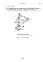
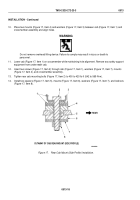
Place two mounts (Figure 17, Item 4) and washers (Figure 17, Item 3) between cab (Figure 17, Item 1) and
crossmember assembly and align holes.
WARNING
Do not remove overhead lifting device. Failure to comply may result in injury or death to
personnel.
11.
Lower cab (Figure 17, Item 1) on crossmember while maintaining hole alignment. Remove any safety support
equipment from underneath cab.
12.
Insert two screws (Figure 17, Item 2) through cab (Figure 17, Item 1), washers (Figure 17, Item 7), mounts
(Figure 17, Item 4), and crossmember assembly.
13.
Tighten rear cab mounting bolts (Figure 17, Item 2) to 400 to 420 lb-ft (542 to 569 N·m).
14.
Install two spacers (Figure 17, Item 5), mounts (Figure 17, Item 6), washers (Figure 17, Item 7), and locknuts
(Figure 17, Item 8).
M3259DAA
1
2
3
4
5
6
REAR
7
8
CUTAWAY OF CAB REAR MOUNT (SIDE PROFILE)
Figure 17.
Rear Cab Mount (Side Profile) Installation.
TM 9-2320-272-23-3
0513
0513-18
Back to Top


