TM-9-2320-272-23-3 - Page 167 of 1469
INSTALLATION
CAUTION
Use care when routing harness. Snagging may result and forceful pulling will cause damage
to harness.
NOTE
Assistant will help with Step (1).
1.
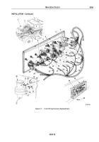
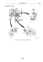
Position front wiring harness (Figure 11, Item 2) in the vehicle (Figure 11, Item 1), routing branches in
approximate positions and through firewall (Figure 11, Item 3).
2.
Connect two wires (Figure 11, Item 24) to spring brake pressure switch (Figure 11, Item 25).
3.
Connect wire (Figure 11, Item 15) to engine temperature gauge (Figure 11, Item 5).
4.
Connect wire (Figure 11, Item 21) to transmission oil temperature gauge (Figure 11, Item 22).
5.
Connect wire (Figure 11, Item 17) to oil pressure gauge (Figure 11, Item 18).
6.
Connect wire (Figure 11, Item 12) to fuel gauge (Figure 11, Item 13).
7.
Connect five wires (Figure 11, Items 10, 11, 14, 16, and 23) to five instrument cluster lights
(Figure
11,
Item
4).
8.
Connect wire (Figure 11, Item 20) to instrument cluster wiring harness (Figure 11, Item 19).
9.
Connect three wires (Figure 11, Item 9) to starter switch (Figure 11, Item 6).
10.
Connect three wires (Figure 11, Item 8) to battery switch (Figure 11, Item 7).
11.
Install fresh air control cable (Figure 11, Item 28) on heater (Figure 11, Item 26) with spring nut
(Figure
11,
Item
27) and cotter pin (Figure 11, Item 33).
12.
Install fresh air control cable (Figure 11, Item 28) on bracket (Figure 11, Item 32) with clamp
(Figure
11,
Item
30), nut (Figure 11, Item 31), and screw (Figure 11, Item 29).
13.
Install instrument cluster assembly (Figure 11, Item 34) on instrument panel (Figure 11, Item 35) with eight
screws (Figure 11, Item 36).
TM 9-2320-272-23-3
0358
0358-18
Back to Top

