TM-9-2320-272-23-3 - Page 169 of 1469
INSTALLATION - Continued
14.
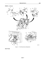
Install wire (Figure 12, Item 15) and battery cables (Figure 12, Items 14 and 16) on terminal clamp
(Figure
12,
Item
3) with screw (Figure 12, Item 17) and nut (Figure 12, Item 13).
15.
Install wire (Figure 12, Item 12) and battery cable (Figure 12, Item 10) on terminal clamp (Figure 12, Item 2)
with screw (Figure 12, Item 11) and nut (Figure 12, Item 9).
16.
Install wire (Figure 12, Item 6) and battery cables (Figure 12, Items 7 and 8) on terminal clamp
(Figure
12,
Item
1) with screw (Figure 12, Item 5) and nut (Figure 12, Item 4).
17.
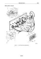
Install diagnostic connector (Figure 12, Item 20) on mounting bracket (Figure 12, Item 33) with two screws
(Figure 12, Item 32), lockwashers (Figure 12, Item 22), and nuts (Figure 12, Item 23).
18.
Install cap chain (Figure 12, Item 28) on mounting bracket (Figure 12, Item 33) with screw
(Figure
12,
Item
30), lockwasher (Figure 12, Item 25), and nut (Figure 12, Item 24).
19.
Install ground wire (Figure 12, Item 21) on mounting bracket (Figure 12, Item 33) with screw
(Figure
12,
Item
31), lockwasher (Figure 12, Item 27), and nut (Figure 12, Item 26).
20.
Install cap (Figure 12, Item 29) on diagnostic connector (Figure 12, Item 20).
NOTE
Perform Step (21) for M936A2 vehicles only.
21.
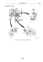
Connect wire (Figure 12, Item 19) to floodlight switch and auxiliary receptacle wire (Figure 12, Item 18).
TM 9-2320-272-23-3
0358
0358-20
Back to Top


