TM-9-2320-272-23-3 - Page 171 of 1469
INSTALLATION - Continued
22.
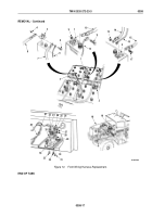
Connect three wires (Figure 13, Item 5) to wires (Figure 13, Item 4).
23.
With selector (Figure 13, Item 2) in N (neutral), install transmission selector (Figure 13, Item 1) on tower
(Figure
13,
Item
3) with four lockwashers (Figure 13, Item 7) and screws (Figure 13, Item 6).
24.
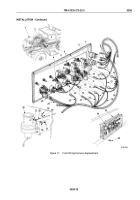
Connect wire (Figure 13, Item 14) to high-beam indicator light (Figure 13, Item 16).
25.
Connect wire (Figure 13, Item 13) to axle lock-in indicator light (Figure 13, Item 17).
26.
Connect wire (Figure 13, Item 12) to spring brake override indicator light (Figure 13, Item 18).
27.
Connect wire (Figure 13, Item 11) to low pressure indicator light (Figure 13, Item 19).
28.
Connect wire (Figure 13, Item 10) to parking brake indicator light (Figure 13, Item 20).
29.
Install warning light panel (Figure 13, Item 8) on instrument panel (Figure 13, Item 9) with four screws
(Figure
13,
Item
15).
NOTE
Perform Step (30) for M929A2, M930A2, M931A2, M932A2, and M936A2 vehicles only.
30.
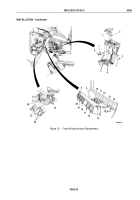
Connect three wires (Figure 13, Item 22) to fuel selector switch (Figure 13, Item 21).
31.
Connect connector (Figure 13, Item 23) to front wheel drive lock-in switch (Figure 13, Item 24).
TM 9-2320-272-23-3
0358
0358-22
Back to Top


