TM-9-2320-272-23-3 - Page 456 of 1469
INSTALLATION
NOTE
Wrap all male pipe threads with antiseize tape before installation.
1.
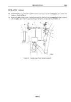
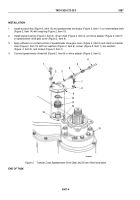
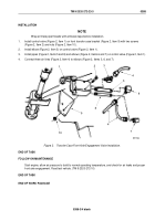
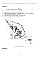
Install control valve (Figure 2, Item 1) on front transfer case bracket (Figure 2, Item 9) with two screws
(Figure 2, Item 2) and nuts (Figure 2, Item 10).
2.
Install elbow (Figure 2, Item 3) on control valve (Figure 2, Item 1).
3.
Install pipes (Figure 2, Items 5 and 8) and elbows (Figure 2, Items 6 and 7) on control valve (Figure 2, Item 1).
4.
Connect three air lines (Figure 2, Item 4) to elbows (Figure 2, Items 3, 6, and 7).
1
2
3
4
6
5
7
4
8
9
10
M7077DAA
Figure 2.
Transfer Case Front Axle Engagement Valve Installation.
END OF TASK
FOLLOW-ON MAINTENANCE
Start engine, allow air pressure to build to normal operating temperature, and check for air leaks and proper
front axle engagement. Road test vehicle. (TM 9-2320-272-10)
END OF TASK
END OF WORK PACKAGE
TM 9-2320-272-23-3
0388
0388-3/4 blank
Back to Top

