TM-9-2320-272-23-4 - Page 1225 of 1393
INSTALLATION
1.
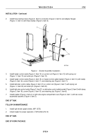
Install heat control cable handle (Figure 3, Item 3), heat control cable (Figure 4, Item 9), defrost control handle
(Figure 3, Item 5), and defrost cable (Figure 3, Item 4) on instrument cluster (Figure 3, Item 6) with two washers
(Figure 3, Item 1) and nuts (Figure 3, Item 2).
2.
Route cables (Figure 3, Item 4) and (Figure 4, Item 9) to diverter brackets (Figure 4, Items 3 and 4).
3.
Install instrument cluster (Figure 3, Item 6) on instrument panel (Figure 3, Item 8) with eight screws
(Figure 3, Item 7).
4.
Push heat control handle (Figure 3, Item 3) and defrost handle (Figure 3, Item 5) in all the way.
M5175DAA
7
6
5
4
3
2
1
8
Figure 3.
Defrost and Heat Controls Installation.
TM 9-2320-272-23-4
0745
0745-4
Back to Top

