TM-9-2320-272-23-4 - Page 1215 of 1393
INSTALLATION - Continued
2.
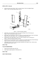
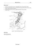
Install three ducting hoses (Figure 3, Item 3) on diverter (Figure 3, Item 5) and adapter flanges
(Figure
3,
Item
4) with three clamps (Figure 3, Item 6).
M5177DAA
3
2
1
Figure 4.
Diverter Assembly Installation.
3.
Install heater control cable (Figure 3, Item 15) on control rod (Figure 3, Item 12) with spring nut
(Figure
3,
Item 13) and cotter pin (Figure 3, Item 14).
4.
Install heater control cable (Figure 3, Item 15) on heater control cable bracket (Figure 4, Item 10) with clamp
(Figure 3, Item 16), screw (Figure 3, Item 17), and retaining clip (Figure 3, Item 11).
5.
Install defroster control cable (Figure 3, Item 21) on control rod (Figure 3, Item 7) with spring nut
(Figure
3,
Item 22) and cotter pin (Figure 3, Item 20).
6.
Install defroster control cable (Figure 3, Item 21) on defroster control cable bracket (Figure 3, Item 9) with clamp
(Figure 3, Item 18), screw (Figure 3, Item 19), and retaining clip (Figure 3, Item 8).
7.
Install bracket (Figure 4, Item 2) to right side engine compartment cowl (Figure 4, Item 1) with two screw
assembled washers (Figure 4, Item 3).
END OF TASK
FOLLOW-ON MAINTENANCE
1.
Install right fender splash shield. (WP
0575)
2.
Check heater for proper operation. (TM 9-2320-272-10)
END OF TASK
END OF WORK PACKAGE
TM 9-2320-272-23-4
0742
0742-4
Back to Top


