TM-9-2320-272-23-4 - Page 1213 of 1393
REMOVAL - Continued
2.
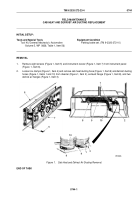
Remove three clamps (Figure 2, Item 6) and ducting hoses (Figure 2, Item 3) from diverter (Figure 2, Item 5)
and three adapter flanges (Figure 2, Item 4).
3.
Remove screw (Figure 2, Item 19), clamp (Figure 2, Item 18), and retaining clip (Figure 2, Item 8) from defroster
control cable bracket (Figure 2, Item 9).
4.
Remove cotter pin (Figure 2, Item 20), defroster control cable (Figure 2, Item 21), and spring nut
(Figure
2,
Item 22) from control rod (Figure 2, Item 7). Discard cotter pin and spring nut.
5.
Remove screw (Figure 2, Item 17), clamp (Figure 2, Item 16), and retaining clip (Figure 2, Item 11) from heater
control cable bracket (Figure 2, Item 10).
6.
Remove cotter pin (Figure 2, Item 14), heater control cable (Figure 2, Item 15), and spring nut
(Figure
2,
Item
13) from control rod (Figure 2, Item 12). Discard cotter pin and spring nut.
CAUTION
Hold personnel hot water heater and brackets in place during removal of diverter. Both mount
to firewall with same screws.
7.
Remove four screw assembled washers (Figure 2, Item 23), cage nuts (Figure 2, Item 2), personnel hot water
heater bracket (Figure 2, Item 24), and diverter (Figure 2, Item 5) from firewall (Figure 2, Item 1).
M5178DAA
7
6
3
6
12
8
9
10
11
6
3
13
14
15
17
16
18
19
20
21
22
23
24
1
2
3
4
5
Figure 2.
Diverter Assembly Removal.
END OF TASK
TM 9-2320-272-23-4
0742
0742-2
Back to Top

