TM-9-2320-272-23-4 - Page 273 of 1393
INSTALLATION - Continued
WARNING
All personnel must stand clear during lifting operations. A snapped chain, or shifting or
swinging load, may result in injury to personnel. Failure to comply may result in injury or death
to personnel.
NOTE
•
Mechanic will handle one guide line and direct hoisting operation. Assistant will handle
other guide line. Second assistant will operate lifting device.
•
Steps (4) and (7) through (9) apply to both left and right sides.
4.
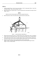
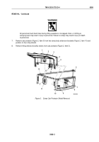
Install six screws (Figure 3, Item 8) on left and right sides of dump body (Figure 3, Item 1).
5.
Hoist dump body (Figure 3, Item 1) clear of shop stand.
6.
Place dump body (Figure 3, Item 1) on subframe (Figure 3, Item 2).
7.
Install two brackets (Figure 3, Item 9) on six screws (Figure 3, Item 8) with six locknuts (Figure 3, Item 13).
Tighten locknuts to 240 lb-ft (325 N·m).
8.
Install screw (Figure 3, Item 12), washer (Figure 3, Item 11), and locknut (Figure 3, Item 10) on each bracket
(Figure 3, Item 9). Tighten locknut to 35 lb-ft (48 N·m).
9.
Align roller arms (Figure 3, Item 15) and thrust plates (Figure 3, Item 2) and install thrust plate pin
(Figure
3,
Item
4).
10.
Remove lifting device, utility chains, and guide lines from dump body (Figure 3, Item 7).
WARNING
Never work under dump body until safety braces are properly positioned. Dump body may
suddenly lower. Failure to comply may result in injury or death to personnel.
11.
Place dump body (Figure 3, Item 7) in raised position (TM 9-2320-272-10).
12.
Place safety braces (Figure 3, Item 14) in proper position (TM 9-2320-272-10).
NOTE
Step (13) applies to both left and right thrust plates.
13.
Install thrust plate pin (Figure 3, Item 4) on thrust plate (Figure 3, Item 2) with screw (Figure 3, Item 5) and
locknut (Figure 3, Item 3). Tighten locknut to 35 lb-ft (48 N·m).
TM 9-2320-272-23-4
0594
0594-6
Back to Top


