TM-9-2320-272-23-4 - Page 277 of 1393
REMOVAL
1.
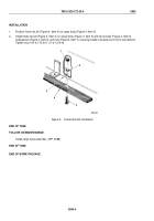
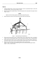
Install two eyebolts (Figure 1, Item 6) into rear holes (Figure 1, Item 5) of cab protector (Figure 1, Item 2) with
two washers (Figure 1, Item 4) and nuts (Figure 1, Item 3).
2.
Attach two utility chains to eyebolts (Figure 1, Item 6) and opposite ends of cab protector front support channel
(Figure 1, Item 1).
NOTE
Mechanic will direct hoisting operation while assistant operates lifting device.
3.
Attach lifting device to center of two utility chains and remove slack from utility chains.
4
5
6
M3015DAA
2
3
1
Figure 1.
Dump Cab Protector Shield Removal.
4.
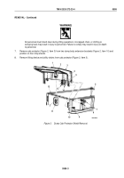
Remove seven locknuts (Figure 2, Item 11), washers (Figure 2, Item 2), screws (Figure 2, Item 1), and washers
(Figure 2, Item 2) from cab protector (Figure 2, Item 3) and dump body (Figure 2, Item 12). Discard locknuts.
5.
Remove eight locknuts (Figure 2, Item 13), washers (Figure 2, Item 14), and screws (Figure 2, Item 9) from
cab protector (Figure 2, Item 3) and two dump body extension brackets (Figure 2, Item 10). Discard locknuts.
6.
Remove four locknuts (Figure 2, Item 4), washers (Figure 2, Item 5), and two screws
(Figure
2,
Items
7
and
8) from cab protector (Figure 2, Item 3) and dump body side support channel
(Figure
2,
Item
6). Discard locknuts.
TM 9-2320-272-23-4
0595
0595-2
Back to Top

