TM-9-2320-272-23-4 - Page 532 of 1393
INSTALLATION - Continued
7.
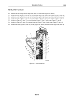
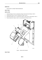
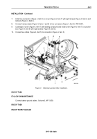
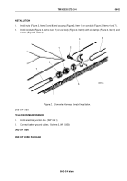
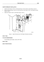
Install two connectors (Figure 4, Item 3) on cover (Figure 4, Item 7) with eight screws (Figure 4, Item 4) and
locknuts (Figure 4, Item 2).
8.
Connect harness leads (Figure 4, Items 1 and 8) to two connectors (Figure 4, Item 3) (TM 9-237).
9.
Coat edge of cover (Figure 4, Item 7) with sealing compound and install cover (Figure 4, Item 7) on junction
box (Figure 4, Item 9) with eight screws (Figure 4, Item 6).
10.
Connect two cables (Figure 4, Item 5) to connectors (Figure 4, Item 3).
M10281DAA
6
7
8
9
1
2
3
4
5
Figure 4.
Electrical Junction Box Installation.
END OF TASK
FOLLOW-ON MAINTENANCE
Connect battery ground cables. (Volume 2, WP
0350)
END OF TASK
END OF WORK PACKAGE
TM 9-2320-272-23-4
0641
0641-5/6 blank
Back to Top

