TM-9-2320-272-23-4 - Page 523 of 1393
INSTALLATION - Continued
26.
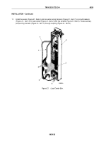
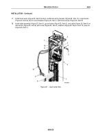
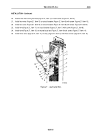
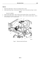
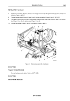
Install two wires (Figure 28, Items 13 and 14), wire (Figure 28, Item 12), right main wiring harness
(Figure
28,
Item
18), clamp (Figure 28, Item 2), and screw (Figure 28, Item 1) in load center
(Figure 28, Item 4) and on three circuit breakers (Figure 28, Items 6, 7, and 8) with three screws
(Figure 28, Items 9, 10, and 11).
27.
Install wire (Figure 28, Item 16) on neutral buss bar (Figure 28, Item 5) with screw (Figure 28, Item 15).
28.
Install three wires (Figure 28, Item 21) on relay (Figure 28, Item 3) with three screws (Figure 28, Item 17).
29.
Install cover (Figure 28, Item 20) on load center (Figure 28, Item 4) with six screws (Figure 28, Item 19).
9
10
11
13
14
15
16
12
18
19
20
21
1
2
17
3
4
5
6
7
8
M3071DAA
Figure 28.
Load Center Box.
END OF TASK
FOLLOW-ON MAINTENANCE
1.
Connect battery ground cables. (Volume 2, WP
0350)
2.
Connect external power source. (TM 9-2320-272-10)
END OF TASK
END OF WORK PACKAGE
TM 9-2320-272-23-4
0639
0639-32
Back to Top

