TM-9-2320-272-23-4 - Page 547 of 1393
INSTALLATION
1.
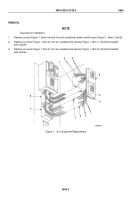
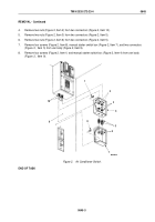
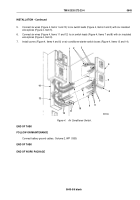
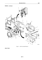
Feed three wires (Figure 4, Items 1, 10, 11, and 12) into manual starter switch box (Figure 4, Item 14).
2.
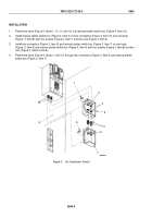
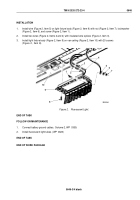
Install manual starter switch box (Figure 3, Item 4) on two connectors (Figure 3, Item 10) and van body
(Figure
3, Item 9) with four screws (Figure 3, Item 1) and two nuts (Figure 3, Item 2).
3.
Install two connectors (Figure 3, Item 5) and manual starter switch box (Figure 3, Item 7) on van body
(Figure
3, Item 9) and manual starter switch box (Figure 3, Item 4) with four screws (Figure 3, Item 8) and two
nuts (Figure 3, Items 3 and 6).
4.
Feed three wires (Figure 4, Items 11 and 12) through two connectors (Figure 3, Item 5) and manual starter
switch box (Figure 3, Item 7).
M3084DAA
7
8
6
5
4
3
2
1
10
9
Figure 3.
Air Conditioner Switch.
TM 9-2320-272-23-4
0645
0645-4
Back to Top


