TM-9-2320-272-23-5 - Page 384 of 623
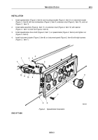
INSTALLATION
1.
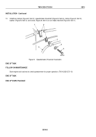
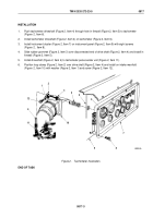
Install speedometer (Figure 2, Item 6) and mounting bracket (Figure 2, Item 5) on instrument cluster
(Figure
2, Item 8) with two lockwashers (Figure 2, Item 4), extension stud (Figure 2, Item 10), and nut
(Figure
2,
Item
3).
2.
Install cable assembly (Figure 2, Item 11) on extension stud (Figure 2, Item 10) with washer
(Figure
2,
Item
12) and nut (Figure 2, Item 3).
3.
Install speedometer drive shaft (Figure 2, Item 1) on speedometer (Figure 2, Item 6) and tighten nut
(Figure
2, Item 2).
4.
Install instrument cluster (Figure 2, Item 8) on instrument panel (Figure 2, Item 9) with eight screws
(Figure
2,
Item 7).
M0200DAA
1
2
3
4
5
6
7
8
9
10
11
12
4
3
Figure 2.
Speedometer Installation.
END OF TASK
TM 9-2320-272-23-5
0815
0815-3
Back to Top


