TM-9-2320-272-23-5 - Page 381 of 623
INSTALLATION - Continued
10.
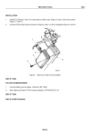
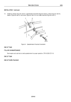
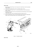
Install two clamps (Figure 8, Item 2), speedometer driveshaft (Figure 8, Item 6), clamp (Figure 8, Item 3),
washer (Figure 8, Item 4), and screw (Figure 8, Item 5) on air intake manifold (Figure 8, Item 1).
2
1
6
3
4
5
M9578DAA
Figure 8.
Speedometer Driveshaft Installation.
END OF TASK
FOLLOW-ON MAINTENANCE
Start engine and road test to check speedometer for proper operation. (TM 9-2320-272-10)
END OF TASK
END OF WORK PACKAGE
TM 9-2320-272-23-5
0814
0814-8
Back to Top


