TM-9-2320-272-23-5 - Page 373 of 623
INSTALLATION
1.
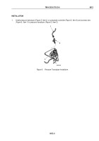
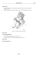
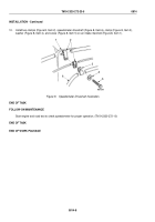
Install ECU (Figure 2, Item 4) on transmission shifter tower (Figure 2, Item 2) with three screws
(Figure
2,
Item
3).
2.
Connect CTIS wiring harness connector (Figure 2, Item 1) to ECU receptacle (Figure 2, Item 5).
1
M6364DAA
5
4
3
2
Figure 2.
Electronic Control Unit Installation.
END OF TASK
FOLLOW-ON MAINTENANCE
1.
Connect battery ground cables. (Volume 2, WP
0350)
2.
Start engine and check CTIS for proper operation. (TM 9-2320-272-10)
END OF TASK
END OF WORK PACKAGE
TM 9-2320-272-23-5
0813
0813-2
Back to Top

