TM-9-2320-272-23-5 - Page 379 of 623
INSTALLATION - Continued
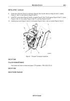
2.
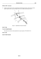
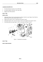
Install grommet (Figure 6, Item 13) on speedometer driveshaft (Figure 6, Item 6) and firewall
(Figure
6,
Item
12).
3.
Connect shaft nut (Figure 6, Item 8) to transfer case input gear cover (Figure 6, Item 9).
4.
Install speedometer driveshaft (Figure 6, Item 6) and clamp (Figure 6, Item 4) on transfer case
(Figure
6,
Item
3) with screw (Figure 6, Item 5). Tighten screw 40 to 65 lb-ft (54 to 88
N·m).
5.
Install bracket (Figure 6, Item 2) on engine bell housing (Figure 6, Item 15) with screw (Figure 6, Item 14).
Tighten screw 25 to 31 lb-ft (34 to 42 N·m).
6.
Install speedometer driveshaft (Figure 6, Item 6) and clamps (Figure 6, Item 16) on bracket
(Figure
6,
Item
2) with screw (Figure 6, Item 17) and nut (Figure 6, Item 1).
7.
Install five tiedown straps (Figure 6, Items 7, 10, and 11) on speedometer driveshaft (Figure 6, Item 6).
5
4
3
9
8
6
2
1
16
17
16
6
15
14
12
13
6
11
10
7
M9588DAA
Figure 6.
Speedometer Driveshaft Installation.
TM 9-2320-272-23-5
0814
0814-6
Back to Top


