TM-9-2320-272-23-5 - Page 370 of 623
INSTALLATION - Continued
8.
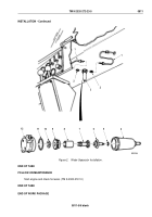
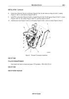
Install clevis (Figure 9, Item 6) on shift lever (Figure 9, Item 14) with clevis pin (Figure 9, Item 7), washer
(Figure
9,
Item
4), and cotter pin (Figure 9, Item 3).
9.
Install PTO control cable (Figure 9, Item 8) on bracket (Figure 9, Item 10) with spacer (Figure 9, Item 11), clamp
(Figure 9, Item 12), two screws (Figure 9, Item 13), and nuts (Figure 9, Item 9).
10.
Install access cover (Figure 9, Item 5) on shift panel (Figure 9, Item 1) with six screws (Figure 9, Item 2).
M10255DAA
14
1
2
3
4
5
6
7
8
9
10
11
12
13
Figure 9.
Pressure Transducer Installation.
END OF TASK
FOLLOW-ON MAINTENANCE
Start engine and check for leaks and proper CTIS operation. (TM 9-2320-272-10)
END OF TASK
END OF WORK PACKAGE
TM 9-2320-272-23-5
0812
0812-9/10 blank
Back to Top

