TM-9-2320-272-23-5 - Page 369 of 623
INSTALLATION - Continued
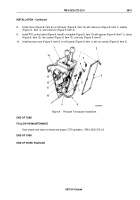
6.
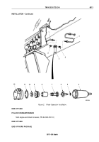
Install clevis (Figure 8, Item 10) on shift lever (Figure 8, Item 3) with clevis pin (Figure 8, Item 12), washer
(Figure
8,
Item
11), and cotter pin (Figure 8, Item 1).
7.
Install front winch control cable (Figure 8, Item 7) on bracket (Figure 8, Item 5) with spacer
(Figure
8,
Item
6), clamp (Figure 8, Item 9), two screws (Figure 8, Item 8), and nuts (Figure 8, Item 4).
M10254DAA
1
2
3
4
5
6
7
8
9
10
11
12
Figure 8.
Pneumatic Transducer Installation.
TM 9-2320-272-23-5
0812
0812-8
Back to Top

