TM-9-2320-272-23-5 - Page 390 of 623
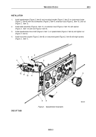
INSTALLATION
1.
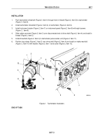
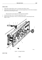
Push tachometer driveshaft (Figure 2, Item 4) through hole in firewall (Figure 2, Item 5) to tachometer
(Figure
2, Item 6).
2.
Install tachometer driveshaft (Figure 2, Item 4) on tachometer (Figure 2, Item 6).
3.
Install instrument cluster (Figure 2, Item 7) on instrument panel (Figure 2, Item 9) with eight screws
(Figure
2,
Item 8).
4.
Slide rubber grommet (Figure 2, Item 3) over disconnected end of drive shaft (Figure 2, Item 4) and install in
firewall (Figure 2, Item 5).
5.
Install driveshaft (Figure 2, Item 4) to tachometer pulse sender unit (Figure 2, Item 11).
6.
Position loop clamp (Figure 2, Item 2) over drive shaft (Figure 2, Item 4) and install on intake manifold
(Figure
2, Item 10) with washer (Figure 2, Item 1) and screw (Figure 2, Item 12).
1
M0202DAA
2
3
4
5
12
4
11
10
9
8
7
6
Figure 2.
Tachometer Installation.
END OF TASK
TM 9-2320-272-23-5
0817
0817-3
Back to Top


