TM-9-2320-272-24-2 - Page 232 of 991
TM 9-2320-272-24-2
3-329. FRONT WINCH REPLACEMENT
THIS TASK COVERS:
a. Removal
b. Installation
INITIAL SETUP:
APPLICABLE
MODELS
All with winch
REFERENCES (TM)
LO 9-2320-272-12
TM 9-2320-272-10
TOOLS
TM 9-2320-272-24P
General mechanic ’s tool kit (Appendix E, Item 1)
Lifting device
Chains
MATERIALS/PARTS
Six locknuts (Appendix D, Item 294)
Eight lockwashers (Appendix D, Item 350)
Cap and plug set (Appendix C, Item 14)
Antiseize type (Appendix C, Item 72)
EQUIPMENT CONDITION
l
Parking brake set (TM 9-2320-272-10)
l
Front winch oil drained (LO 9-2320-272-12)
l
Front bumper removed (para. 3-243).
l
Front winch cable removed (para. 3-327).
GENERAL SAFETY INSTRUCTIONS
All personnel must stand clear during lifting
operations.
a. Removal
CAUTION
When disconnecting hydraulic lines and hoses, plug all openings to
prevent dirt from entering and causing damage to internal parts.
NOTE
l
Have drainage container ready to catch oil.
l
Tag all hydraulic lines for installation.
1.
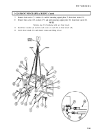
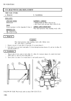
Disconnect oil supply hose (26) from rear elbow (27) on winch motor (28).
2.
Disconnect oil return hose (25) from front elbow (24) on winch motor (28).
3.
Remove four screws (2), lockwashers (3), and washers (4) from left mounting support plate (5) and
left frame rail extension (11). Discard lockwashers (3).
4.
Remove three locknuts (12), screws (8), and washers (9) from left inner support plate bracket (10)
and left mounting support plate (5). Discard locknuts (12).
5.
Remove four screws (1), lockwashers (23), and washers (22) from right mounting support plate (21)
and right frame rail extension (15). Discard lockwashers (23).
6.
Remove three locknuts (13), screws (17), and washers (16) from right inner support plate bracket (14)
and right mounting support plate (21). Discard locknuts (13).
7.
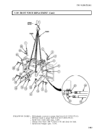
Position chains on front winch (18) and attach to lifting device.
WARNING
All personnel must stand clear during lifting operations. A
snapped cable, or swinging or shifting load, may result in injury to
personnel.
NOTE
Assistant will help with step 8.
8.
Remove front winch (18) from frame rail extensions (11) and (15).
3-840
Back to Top


