TM-9-2320-272-24-2 - Page 236 of 991
TM 9-2320-272-24-2
3-330. REAR WINCH ADJUSTMENT
THIS TASK COVERS:
a. Cable Tensioner Check
b. Cable Tensioner Adjustment
INITIAL SETUP:
APPLICABLE MODELS
REFERENCES (TM)
M936/A1/A2
TM 9-2320-272-10
TOOLS
TM 9-2320-272-24P
General mechanic ’s tool kit (Appendix E, Item 1)
EQUIPMENT
CONDITION
Test rod. 5/8 in. diameter
Rear winch cable removed (para. 3-331).
a. Cable Tensioner Check
1.
Start engine (TM 9-2320-272-10) and allow air system to build to normal operating pressure.
2.
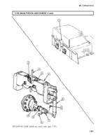
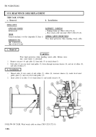
Place cable tensioner control valve lever (1) in ON position.
3.
Place test rod (3) between sheaves (2). If test rod (3) cannot be inserted or fits loosely, adjust cable
tension (task b).
4.
Stop engine (TM 9-2320-272-10) and remove test rod (3) if adjustment is not required.
b. Cable Tensioner Adjustment
1.
Remove cotter pin (6), pin (8), and pushrod yoke (7) from pivot arm (5).
2.
Place test rod (3) between sheaves (2) on cable tensioner (4).
3.
Loosen jamnut (9) on pushrod (10).
4.
Position pivot arm (5) so sheaves (2) are against test rod (3).
5.
Turn pushrod yoke (7) until holes in pushrod (10) and pivot arm (5) align.
6.
Install pushrod yoke (7) on pivot arm (5) with pin (8) and pin (6). Tighten jamnut (9).
7.
Place tensioner control valve lever (1) in OFF position and remove test rod (3) from sheaves (2).
8.
Stop engine (TM 9-2320-272-10).
3-844
Back to Top


