TM-9-2320-272-24-2 - Page 774 of 991
4-7. PREPARING
TM 9-2320-272-24-2
5.
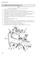
Remove two screws (4), lockwashers (5), washers (3), clamps (l), and transmission oil cooler lines (2)
from access plate (6). Discard lockwashers (5).
6.
Install two washers (3), new lockwashers (5), and screws (4) on access plate (6). Tag oil cooler
lines (2) for installation.
7.
Disconnect air line (7) from evaporator bottle (9).
8.
Remove three locknuts (10), screws (8), evaporator bottle (9), and bracket (12) from primer pump
bracket (11). Discard locknuts (10).
9.
Disconnect two air lines (19) from elbows (18).
10.
Remove two elbows (18) from air compressor (22).
11.
Disconnect air line (21) from fitting (20).
12.
Remove two screws (16), lockwashers (17), clamps (14), air line (15), and primer pump bracket (11)
from engine block (13). Discard lockwashers (17).
1.
2.
3.
4.
5.
6.
7.
8.
9.
NOTE
Wrap all male pipe threads with antiseize tape before installation.
Install primer pump bracket (11), clamps (14), and air line (15) on engine block (13) with two
lockwashers (17) and screws (16).
Connect air line (21) to fitting (20).
Install two elbows (18) on air compressor (22).
Connect two air lines (19) to elbows (18).
Install evaporator bottle (9) and bracket (12) on primer pump bracket (11) with three screws (8) and
locknuts (10).
Connect air line (7) to evaporator bottle (9).
Remove two screws (4), lockwashers (5), and washers (3), from access plate (6). Discard lock-
washers (5).
Install two transmission oil cooler lines (2) on access plate (6) with two clamps (1), washers (3),
lockwashers (5), and screws (4).
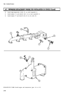
Install water temperature sending unit (5) on water manifold (1).
4-92
Back to Top

