TM-9-2320-280-20-3 - Page 1078 of 1168
TM 9-2320-280-20-3
Change 1
D - 1 0 5
Section II.
I L L U S T R ATED MANUFACTURING INSTRUCTIONS (Cont'd)
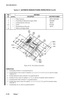
Figure D-113. Test Module Assembly (Cont’d).
INSTRUCTIONS (CONT’D):
31. Place electrical insulation sleeving (3) over wire (10) marked 1 on plug connector.
32. Place twenty-four sections of insulation sleeving (3) over connected wires (6) and (11) on LEDs (5) and
heat-shrink into position.
33. Install four screws (4) in mount holes (12) on mini-box top section (1) and position four spacers (2) and
punch board (7) on screws (4) and secure with four washers (8) and nuts (9).
I T E M
M AT E R
I A L S
N O .
R E Q ’ D
D E S C R
I P T
I O N
N S N / PA RT NUMBER
2
4
Spacer
313-1437-024
3
25
Insulation Sleeving (install in figure D-110)
4
4
Screw
8
4
Washer
9
4
Nut
Back to Top


